H.P.W.® › Installing and setting up the H.P.W.® manifold step by step
H.P.W.® · installation and setup

Installing and setting up the H.P.W.® manifold step by step

A practical guide from positioning the cabinet and connecting PEX-AL-PEX 16 × 2 pipe, through filling and pressure testing, to hydraulic balancing with 0–5 l/min flow meters and room temperature control.

updateUpdated: verifiedTechnically reviewed by the ATRIA SK s.r.o. technicians

handymanQuick mounting on bracketslinkCompression fittings 16 × 2 EKcompressTest pressure max. 10 barspeedBalancing 0–5 l/min
menu_bookGuide

Who this guide is for and what you will need

We have prepared this guide for homeowners who are installing underfloor heating themselves or want to understand the work of their installation company, and for installers working with H.P.W.® manifolds for the first time. The procedure applies to all sizes from 2 to 12 circuits – they differ only in length, while the equipment and the installation method are the same.

The manifold is supplied with shut-off valves, regulating fittings with flow meters, an automatic air vent and a drain valve. Before installation, also prepare the compression fittings for the pipe (two per circuit), 1" ball valves with thermometer (red for the flow, blue for the return) and a cabinet of the appropriate size. How to choose the cabinet by number of circuits is explained on the page Manifold cabinets.

Tools and equipment

  • a cutter for multilayer (plastic-aluminium) pipe (scissor or rotary type), or a calibration tool to round and chamfer the pipe end,
  • open-ended or adjustable spanners of the appropriate size, ideally a torque wrench,
  • a drill, wall plugs and screws for fixing the cabinet and brackets, a spirit level,
  • a pressure test pump with pressure gauge,
  • a filling hose and a drain hose, a bucket, a cloth,
  • a marker or labels for marking the circuits.
A skilled DIYer can install the manifold and its accessories. We recommend that connection to a working heating system, setting up the heat source and the electrical wiring of the pump or thermostats be carried out, or at least checked, by a professional.
format_list_numberedProcedure in brief

Installing the manifold in 9 steps

1. Positioning

Choose a location as close as possible to the centre of the heated floor area, with easy access and enough space for the cabinet.

2. Cabinet and brackets

Install the cabinet (recessed into or mounted on the wall), adjust its height and depth to suit the floor and hang the manifold on the brackets.

3. Ball valves

Screw on the 1" ball valves – red on the flow (upper bar), blue on the return (lower bar).

4. Flow and return

Connect the pipes from the heat source or mixing unit. With a higher source temperature, do not forget the mixing unit and a safety thermostat.

5. Circuits

Connect the pipe of each circuit with an EK compression fitting – the start of the loop to the flow, the end to the return under the same circuit number.

6. Filling and flushing

Fill the system and flush it circuit by circuit until water without bubbles comes out of the drain hose.

7. Pressure test

Pressurise the system as specified in the design – never above the manifold's max. test pressure of 10 bar – and check all joints for leaks.

8. Balancing

Use the flow meters to set the flow rate of each circuit according to its length and heat demand, then lock the setting.

9. Controls

Fit thermostatic heads or actuators on the return, set the pump and record the values in the commissioning report.

placeSteps 1 and 2

Positioning the manifold and installing the cabinet

The position of the manifold affects the whole underfloor heating design. The closer it is to the centre of the heated area, the shorter the supply sections to the individual rooms. The supply pipes usually run through the hallway, and a dense bundle of pipes can overheat it unnecessarily – another reason why a central position is better than a corner of the house. In houses with several floors, a separate manifold is usually designed for each floor.

What to consider when choosing the location

  • Access – you will come back to the manifold for balancing, bleeding and replacing actuators. Do not block it with furniture or tiling without an access door.
  • Height – mount the manifold so that the pipes can enter the floor from the bar in a smooth bend and so that there is enough space below the lower bar for the fittings and a spanner.
  • Wall – a flush-mounted cabinet needs a sufficiently thick wall; for thin partition walls or renovations, a surface-mounted cabinet is more practical.
  • Electricity – if you are planning actuators and room thermostats, allow for a socket or a power supply for the wiring centre near the cabinet.

The cabinet and hanging the manifold

Manifold cabinets are either recessed into the wall (flush-mounted) or fixed to the wall (surface-mounted). Each type allows the height and depth to be adjusted to suit the floor – H.P.W. flush-mounted cabinets have a height adjustable within approximately 575–665 mm and a depth of 110–175 mm (120–186 mm for some types). Install the cabinet level and align its bottom edge with the planned finished floor height.

The H.P.W. manifold is mounted on an aluminium bracket. Thanks to quick-mount technology, you simply hang it onto the brackets in the cabinet and tighten the screws. The design of the new generation of manifolds was optimised precisely to make installation in the cabinet as easy as possible for heating engineers. Before final tightening, check that the bars are horizontal.

Before buying a cabinet, compare its width with the length of the manifold including ball valves (230 mm for 2 circuits up to 735 mm for 12 circuits) and leave a reserve for connecting the pipes and working with a spanner. Recommended combinations are given in the table on the page Accessories.
plumbingSteps 3 and 4

Connecting the flow and return

The H.P.W. manifold has 1" flow and return connections. The upper bar with flow meters is the flow (hot water from the source), the lower bar with thermostatic valves is the return. We always recommend fitting a pair of ball valves between the manifold and the pipes from the source – they let you isolate the entire manifold with a quarter turn, for example when replacing an actuator or during a repair, without draining the whole system.

Ball valves – straight or angled

H.P.W. ball valves are screwed onto the end of the manifold with a 1" half-union connection. They have a built-in 0–80 °C thermometer, so you can see the flow and return temperatures right at the manifold. The colour-coded butterfly handle makes orientation easy: red belongs on the flow, blue on the return.

  • Straight valve (ROZDZ.ZAW.CZ / ROZDZ.ZAW.N) – the pipe from the source continues in line with the manifold; suitable when the supply comes from the side.
  • Angled valve (ROZDZ.ZAW.K.CZ / ROZDZ.ZAW.K.N) – turns the connection through 90°; practical when the pipe comes from below (out of the floor) or from above and there is no room for a bend in the cabinet.

Seal threaded joints without a flat gasket in the usual way – with PTFE tape or hemp with sealing paste. On joints with a flat gasket, do not leave the gasket out and make sure it is clean and correctly seated.

Flow water temperature

Underfloor heating works with low water temperatures. If the heat source supplies water at a temperature suitable for radiators (for example a solid fuel boiler or an older radiator system), you must not connect it directly to the underfloor heating manifold. A mixing unit (mixing valve with pump) and a safety contact thermostat, which switches off the underfloor circuit pump when the set temperature is exceeded, belong between the source and the manifold. Although the manifold's max. permissible operating temperature is +80 °C, the decisive factors are the screed and the floor covering – details can be found in the section on mixing and the safety thermostat below.

Low-temperature sources such as a heat pump or a condensing boiler with weather-compensated control are often connected to underfloor heating directly – the water temperature is then controlled by the source's own controller. Even here, a safety thermostat is worthwhile as protection against incorrect settings.

linkStep 5

Pipe and compression fittings for connecting the circuits

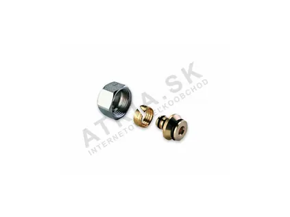
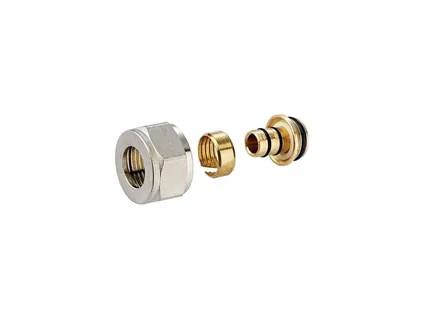
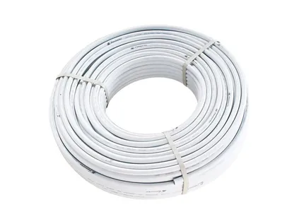
For H.P.W. manifolds we recommend PEX-AL-PEX 16 × 2 multilayer pipe and compression fittings with an EK (Eurocone) connection. You need two fittings for each circuit.

buildStep 5

How to connect PEX-AL-PEX 16 × 2 correctly with an EK compression fitting

The circuit outlets on the H.P.W. manifold have an EK (Eurocone) connection. A compression fitting consists of a nut, a compression ring and an insert with an EPDM O-ring. When the nut is tightened, the inner ring is compressed and grips the pipe firmly. The joint can be dismantled – simply unscrew the fitting and remove the pipe.

How to install the fitting

  1. Cut the pipe squarely with a cutter for multilayer pipe. Do not use a saw – it leaves burrs and deforms the cross-section.
  2. Calibrate and chamfer the pipe end with a calibration tool so that the cross-section is round and the edge does not damage the O-ring when the pipe is pushed on.
  3. Slide the nut and compression ring onto the pipe in the correct order and direction – the nut with its thread facing the manifold outlet.
  4. Check cleanliness and the O-ring – everything must be clean and the sealing O-ring must not be damaged.
  5. Push the pipe onto the insert as far as it will go. If necessary, lightly moisten the O-ring – exclusively with a silicone-based lubricant. EPDM rubber parts must never be lubricated with mineral oils.
  6. Screw the nut onto the EK outlet by hand and then tighten it with a spanner of the appropriate size. The tightening torque for the ALPEX 16 × 2 ALU-EK fitting (500684) is 25–35 Nm, for the RCS16 fitting 30–40 Nm.
  7. Label the circuit – write the circuit number and the room on both the pipe and the manifold.

Rules worth following

  • The start and end of the same loop belong on the flow and return under the same circuit number. Mixing them up is one of the most common mistakes – the circuit then cannot be controlled properly.
  • The fitting size must exactly match the pipe – a 16 × 2 fitting only for 16 × 2 mm pipe.
  • PEX-AL-PEX pipe holds its shape after bending thanks to the aluminium layer and does not spring back. Form the bends below the manifold smoothly, without kinks, and do not put the pipe under tension – the joint must not be loaded by pulling forces.
  • Supply pipes in areas that are not meant to be heated (for example running closely side by side in a hallway) should be laid in a protective sleeve or insulated so that they do not overheat the hallway.

The pipe is fixed to the floor insulation with pipe clips or with staples into a system board with a grid. Accessories for laying the pipe can be found on the page Pipe, fittings and system board.

waterStep 6

Filling, flushing and bleeding

Air is the most common reason why an underfloor heating circuit does not heat. The pipe in the floor is long and laid horizontally, so air will not escape from it by itself – it has to be pushed out of the circuits by a flow of water. That is why underfloor heating is not simply filled via the heat source, but flushed circuit by circuit.

Flushing procedure

  1. Close the ball valves so that the flushing water does not go into the heat source.
  2. Connect a filling hose on the flow side (from the mains water supply or a filling pump) and a drain hose on the return side leading to a bucket or a drain – to the manifold's drain valves, or to the fill and drain valves in the supply pipes.
  3. Use the shut-off valves to close all circuits except the first one.
  4. Run water until a continuous stream without bubbles comes out of the drain hose. A long circuit takes longer – the water content of 16 × 2 pipe is 0.113 l per metre, so a circuit with 100 m of pipe holds approximately 11.3 litres of water.
  5. Close the first circuit, open the second and repeat the procedure until all circuits have been flushed.
  6. Finally, open all circuits and the ball valves, top up the system to operating pressure and let the automatic air vent do its work.

The automatic air vent on the H.P.W. manifold then continuously removes the air that is released from the water as it heats up during the first days and weeks of operation. After a few days of heating, check the system pressure and top up with water if necessary. If your assembly has a manual air vent, bleed it by hand – preferably with the pump stopped, when the air collects in the upper part of the bar.

H.P.W. manifolds work with heating water, cooling water and water mixtures with a standard anti-corrosion antifreeze additive. If you use a heating water additive, follow the instructions of its manufacturer and the specifications of the heat source manufacturer.
compressStep 7

Pressure test before the screed is poured

The pressure test is the last chance to find a leak before the pipe disappears under the screed. It is carried out after filling and bleeding, always before the screed is poured. The test pressure and the duration of the test are specified by the design or the installation company – for the H.P.W. manifold, however, there is a fixed upper limit: the max. test pressure is 10 bar. The manifold's max. permissible operating pressure is 6 bar.

Procedure

  1. Check that all fittings are tightened, the circuits are open and the system has been bled.
  2. If ball valves are fitted, isolate the heat source and other equipment with a lower permissible pressure by closing the ball valves, so that they are not exposed to the test pressure.
  3. Connect the pressure pump with gauge and gradually increase the pressure to the value specified in the design – never above 10 bar.
  4. During the test, check every joint visually and by touch – the fittings on the manifold, the ball valves and any couplings in the supply pipes.
  5. Watch the pressure gauge. A small pressure drop at the beginning is normal with plastic pipes (the pipe expands slightly and the water temperature changes), but a pressure that keeps falling without an obvious cause indicates a leak.
  6. Record the result in a test report: date, test pressure, test duration, final pressure and signature.

It is recommended to keep the pipes under pressure while the screed is being poured. Any damage to the pipe caused by foot traffic or work with the screed will then show up immediately as a pressure drop and can be repaired before the screed hardens.

Initial heat-up

After pouring, the screed must not be heated straight away. Start heating for the first time only after the period specified by the screed manufacturer has elapsed, and raise the water temperature gradually. The exact heat-up programme (starting temperature, rate of increase, holding time) is specified by the manufacturer of the screed and the floor covering.

speedStep 8

Hydraulic balancing with 0–5 l/min flow meters

The circuits in a house differ in both length and heat demand. Water always takes the path of least resistance, so without balancing short circuits would receive too much water and long ones too little. The result is overheated and cold spots, an unnecessarily high water temperature and higher energy consumption. The flow meters on the H.P.W. manifold measure in the range 0–5 l/min with an accuracy of ±10 %; they are dual-regulating and the setting can be locked.

If you have a system design

An underfloor heating design specifies the required flow rate for each circuit in l/min (or in kg/h – 60 kg/h corresponds to approximately 1 l/min). You simply set these values on the flow meters. This is the most accurate method, because the designer knows the heat losses of each room.

Without a design – calculation from heat demand

The required flow rate of a circuit can be estimated using the formula:

Flow rate [l/min] = Circuit output [W] / (69.8 × ΔT [K])

where ΔT is the temperature difference between flow and return. Underfloor heating is commonly designed for 5 to 10 K. Example: a living room circuit is to deliver 900 W at ΔT = 5 K, so the flow rate will be 900 / (69.8 × 5) ≈ 2.6 l/min. The figure 69.8 comes from the heat capacity of water – one litre per minute transfers 69.8 W for every kelvin of temperature difference.

If you do not know the heat demand either – the proportional method based on length

If all circuits are laid with a similar spacing and the rooms have similar heat losses per m², a simple proportional method can be used. The output of a circuit is roughly proportional to the area it covers, and therefore to the length of its pipe. The longest (most demanding) circuit is assigned a flow rate using the formula above, and the other circuits are set in proportion to their length relative to the longest circuit. An illustrative example is given in the table below.

table_chartExample

Balancing example – circuit length and flow meter setting

Illustrative calculation using the proportional method for a manifold with 6 circuits. The longest circuit (95 m) is assigned a flow rate of 2.5 l/min; the other circuits are set in proportion to their length.

CircuitRoomCircuit length incl. supply sectionRatio to the longestFlow meter setting
1Living room – circuit A95 m1.002.5 l/min (fully open)
2Living room – circuit B90 m0.952.4 l/min
3Bedroom80 m0.842.1 l/min
4Children's room70 m0.741.8 l/min
5Bathroom50 m0.531.3 l/min
6Hallway40 m0.421.1 l/min
Total425 m11.2 l/min (≈ 0.67 m³/h)

The values are for illustration only – they explain the method and are not settings for a specific house. Bathrooms tend to have a higher heat demand per m² (higher required temperature); if the bathroom is laid more densely (10 cm spacing), it has more pipe per m² and the method partly takes this into account. After a few days of operation, fine-tune the settings according to the actual room temperatures.

tuneStep 8 in detail

Balancing step by step

1. Everything open

Open the ball valves and all circuits. Leave the thermostatic heads or actuators fully open for now, or remove them temporarily.

2. System bled

Balancing only makes sense in a system that has been bled. Air in a circuit distorts both the flow meter reading and the resulting temperatures.

3. Pump at medium speed

Start the pump; with a three-speed pump, begin at the middle setting. Leave the heat source running in its normal mode.

4. Longest circuit open

Leave the circuit with the highest flow demand fully open – it determines whether the pump is sufficient. If even fully open it does not reach the required flow rate, increase the pump speed.

5. Throttle the other circuits

Start with the shortest circuit. Turn the flow meter to set the calculated flow rate and read the value on the scale.

6. Second round of checks

A change in one circuit affects the pressure conditions in the others. Go through all circuits once more and correct the values – two or three rounds are usually enough.

7. Pump as low as possible

If all circuits reach the required flow rate with a margin, try reducing the pump speed. You will save electricity and reduce flow noise.

8. Locking and record

Lock the flow meter settings and record the values in the commissioning report or on a label on the cabinet door. During later checks you will know straight away how the system is supposed to work.

9. Fine-tuning after operation

After a few days of heating, compare the room temperatures. Slightly increase the flow rate to a cooler room and reduce it for an overheated one.

thermostatStep 9

Thermostatic heads and actuators on the return

The lower bar of the H.P.W. manifold has integrated thermostatic (return) valves – one on each circuit. Thermostatic heads or actuators are fitted directly onto them. While the flow meter determines the maximum amount of water that can flow through the circuit, the thermostatic valve on the return closes and opens the circuit as required – and in this way controls the room temperature.

Three levels of control

  • No room control – the circuits are only balanced with the flow meters and the temperature is controlled by the heat source (for example with weather compensation). The simplest option, but without the possibility of a different temperature in each room.
  • Thermostatic head on the valve – an inexpensive, maintenance-free solution. The head senses the temperature at the manifold, not in the room, so it acts more as a limit on the circuit water temperature than as genuine room control.
  • Actuators and room thermostats – the actuator on the valve is controlled by the room thermostat in the respective room. The circuit closes when the required temperature is reached in the room and opens when the temperature drops. This is the most convenient and the most economical solution.

What to consider with actuators

  • Connection – check that the head or actuator matches the valve connection on the manifold. If you are not sure, contact us before buying.
  • Normally closed or normally open – actuators are made in both versions. Choose the type that suits your control system.
  • Pump with closed circuits – if all circuits close at the same time, the pump would run against closed valves. The solution is to switch the pump off via the controls (when no thermostat is calling for heat), or to leave one circuit without an actuator, for example in the bathroom.
  • Sensible zoning – underfloor heating responds slowly. Frequent large temperature changes in the rooms are less advantageous than a stable temperature with a moderate setback.
device_thermostatWater temperature

Mixing, safety thermostat and circulation pump

Underfloor heating needs a low water temperature. If the same heat source also supplies radiators or a hot water cylinder, or if it is a solid fuel boiler, the water for the underfloor heating is prepared in a mixing circuit: a mixing valve blends cooler return water into the hot water from the source, and a separate circulation pump delivers it to the manifold.

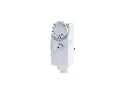
AVANSA TH 2A safety contact thermostat

The AVANSA TH 2A (312034) contact thermostat is attached with a spring directly to the pipe or to the manifold. When the set temperature is reached, its bimetal switches the contact – wired as a cut-out, it interrupts the live supply to the underfloor circuit pump when the flow water is too hot. The temperature range is 20–90 °C, the switching differential 8–3 °C, the voltage 230 V and the protection rating IP 20; it is mounted on pipes up to 2" in diameter. Set the cut-out temperature according to the design and the recommendations of the screed and floor covering manufacturers – in standard wet systems, the safety limit is set well below the manifold's max. permissible operating temperature (+80 °C). Leave the electrical wiring to an electrician.

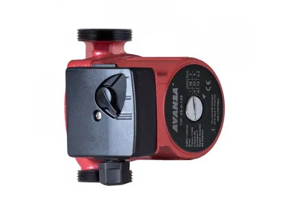
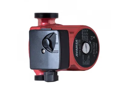
AVANSA 25/4/130 and 25/6/130 circulation pumps

Three-speed AVANSA circulation pumps with a 130 mm installation length and a 6/4" connection thread are suitable for the underfloor heating mixing circuit or for circulating water in the system. The speed is changed with a switch on the terminal box.

  • AVANSA 25/4/130 – head 4 m, max. flow 48 l/min, power input 72/53/38 W. For smaller systems with fewer, shorter circuits.
  • AVANSA 25/6/130 – head 6 m, max. flow 55 l/min, power input 93/67/46 W. For larger systems and longer circuits.

The pump head must cover the pressure losses of the circuit – these depend on the pipe length, the number of circuits and the resistance of the fittings. For a typical family house, a pump with a head of up to 6 m is usually sufficient. When balancing, set the lowest speed at which even the most demanding circuit reaches the required flow rate. More about AVANSA pumps and thermostats can be found at avansa-europe.com.

Radiators in the same system

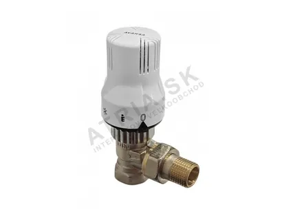
If the H.P.W. manifold supplies radiators (manifold-based distribution) or you have radiators in the house in addition to underfloor heating, the AVANSA TH6 thermostatic set is suitable for radiators with side connection – a DN15 thermostatic valve in a 1/2" angled version with a liquid-filled head according to EN 215. The head scale corresponds to temperatures from 6 °C (*) through 20 °C (setting 3) to 28 °C (setting 5). For radiators with bottom connection, the HPW Set2 regulating set is available – you will find it among the accessories.

settings_input_componentControls

Controls and pumps for the manifold

Safety thermostat, thermostatic set for radiators and circulation pumps for the underfloor heating mixing circuit.

warningCommon mistakes

The most common mistakes when installing and setting up a manifold

MistakeConsequenceHow to avoid it
Start and end of a circuit swappedThe circuit cannot be controlled properly; the thermostatic valve works on the wrong sideLabel the pipe ends while laying and connect them under the same circuit number
Circuits not flushed individuallyAir bubbles, gurgling, the circuit does not heatFlush circuit by circuit until water comes out without bubbles
Pipe cut with a saw, end not calibratedDamaged O-ring, leaking fittingUse a multilayer pipe cutter and a calibration tool, check the O-ring
EPDM seal lubricated with mineral oilDamaged seal and gradual leakageUse only silicone-based lubricant
Fitting under- or over-tightenedLeak or damaged jointObserve the tightening torque: 25–35 Nm (500684), 30–40 Nm (RCS16)
Pressure test above 10 barRisk of damage to the manifold and fittingsTest pressure according to the design, never above the max. test pressure of 10 bar
Underfloor heating connected directly to a high-temperature sourceOverheating of the screed and floor coveringMixing circuit and safety contact thermostat on the flow
Circuits not balancedShort circuits overheated, long ones cold, higher water temperatureSet the flow meters according to the design or using the proportional method
Circuits too longInsufficient flow even with the flow meter fully openDesign circuits up to approx. 80–100 m including the supply section
Cabinet without spare spaceFittings cannot be tightened, ball valves do not fitCompare the length of the manifold with ball valves to the width of the cabinet
Screed poured without pressure in the pipesPipe damage is only discovered after the screed has hardenedKeep the pipes under pressure while the screed is being poured
event_repeatOperation

Commissioning and regular checks

After balancing and the first heating season, the system should run without any intervention. Even so, it is worth spending a few minutes on the manifold once a year, ideally at the start of the heating season.

  • System pressure – check the pressure gauge at the heat source. If the pressure keeps falling, look for a leak; regular topping up brings oxygen and impurities into the system.
  • Air venting – check that the automatic air vent is not dripping and that there is no gurgling from the circuits.
  • Flow meters – compare the readings with the values in the commissioning report. A significantly lower flow in one circuit may indicate air or dirt.
  • Thermometers on the ball valves – the difference between the flow and return temperatures shows how the system is releasing heat. A very small difference at a high flow rate indicates that the pump is running unnecessarily fast.
  • Actuators – check that the circuits open when the thermostat calls for heat and close when the demand ends.
  • Joints – visually check the fittings and ball valves for any signs of moisture.

If you need to shut off one circuit (for example when replacing the floor covering), close it on both the flow and the return – the other rooms will continue to be heated. For work on the whole manifold, close the ball valves; there is no need to drain the system.

Everything you need for the installation – ball valves, cabinets, pipe and fittings – can be found on the page Accessories, and a comparison of brass and stainless steel manifolds in the section Stainless steel manifolds. Back to the H.P.W. manifold overview.

helpFAQ

Questions about installation and setup

What torque should the compression fittings be tightened to?
The ALPEX 16 × 2 ALU-EK compression fitting (500684) is tightened to 25–35 Nm, the RCS16 fitting to 30–40 Nm. First screw the nut on by hand and only then tighten it with a spanner of the appropriate size.
Can I lubricate the O-ring of the fitting?
Only with a silicone-based lubricant. EPDM rubber parts must never be lubricated with mineral oils – the seal would be damaged.
At what pressure should the pressure test be carried out?
The test pressure and the duration of the test are specified by the design or the installation company. For the H.P.W. manifold, the max. test pressure is 10 bar and the max. permissible operating pressure is 6 bar. Isolate equipment with a lower permissible pressure using the ball valves during the test.
How do I set the flow meters if I have no system design?
Determine the flow rate for the longest circuit using the formula Flow rate [l/min] = Output [W] / (69.8 × ΔT [K]) and set the other circuits in proportion to their length relative to the longest one. An example can be found in the table above on this page. After a few days of operation, fine-tune the settings according to the actual temperatures.
Why is one circuit not heating?
Most often there is air in it – flush it separately. Also check that both the flow meter and the return valve are open, that the actuator responds to the thermostat and that the ends of the circuit are not swapped. If the circuit does not reach the required flow rate even when fully open, it may be too long or the pump may be set to too low a speed.
Can I connect underfloor heating directly to the boiler?
Only if the source supplies water at a temperature suitable for underfloor heating (for example a heat pump or a condensing boiler with weather-compensated control). With a high-temperature source, a mixing circuit with a pump and a safety contact thermostat belong between the boiler and the manifold.
Which ball valve goes on the flow and which on the return?
The valve with the red butterfly handle goes on the flow (the upper bar with flow meters), the valve with the blue butterfly handle on the return (the lower bar with thermostatic valves). The valves are always fitted as a pair.
Which pump should I choose for the mixing circuit?
For smaller systems with shorter circuits, the AVANSA 25/4/130 (head 4 m, max. 48 l/min) is sufficient; for larger systems and longer circuits, choose the AVANSA 25/6/130 (head 6 m, max. 55 l/min). Both have three speeds – set the lowest one at which all circuits reach the required flow rate.
Does the manifold need to be bled manually?
When filling for the first time, the circuits must be flushed individually so that the air is pushed out of the long pipes in the floor. In operation, the air is then removed continuously by the automatic air vent. If your assembly has a manual air vent, bleed it as needed, preferably with the pump stopped.
Does the installation have to be carried out by a professional?
A skilled DIYer can install the cabinet and the manifold and connect the circuits. We recommend entrusting the connection to a working heating system, the setup of the heat source and the electrical wiring of the pump and thermostats to a professional, or at least having them checked by one. We will be happy to answer your technical questions on +421 917 133 664 (Monday – Friday, 7:30 – 15:30 CET).
How many circuits can one H.P.W.® manifold have?
H.P.W.® manifolds are made with 2 to 12 circuits – the equipment and the installation procedure are the same for all sizes, and only the length differs. The length without ball valves is 145 mm for 2 circuits, and each further circuit adds 50 mm. In multi-storey houses, a separate manifold is usually designed for each floor. You will find the sizes in the overview of brass manifolds.
How long can one underfloor heating circuit be?
With PEX-AL-PEX 16 × 2 pipe, a circuit of roughly up to 90 m including the connections to the manifold is a rule of thumb; a longer circuit has higher pressure losses and is harder to balance. The exact length and number of circuits are determined by the design.
How much water is in one underfloor heating circuit?
PEX-AL-PEX 16 × 2 pipe holds 0.113 litres of water per metre, so a circuit with 100 m of pipe holds approximately 11.3 litres. You can also estimate the flushing time from this – a long circuit has to be flushed for longer, until the water from the drain hose comes out free of bubbles. You will find the pipe consumption by spacing in the table on the page Pipe and compression fittings.
Can the H.P.W.® manifold also be used for cooling or with antifreeze?
Yes. H.P.W.® manifolds are designed for both heating and cooling systems and work with heating water, cooling water and water mixtures with a standard anti-corrosion antifreeze additive. For additives in the water, follow the instructions of their manufacturer and of the heat source manufacturer.
How do I shut off just one circuit, for example when replacing a floor?
Close the circuit on the flow (flow meter) and on the return (thermostatic valve) – the other rooms keep heating. If you are working on the whole manifold, close the red and blue ball valves; there is no need to drain the system. Before reopening, check the flow meter setting against the commissioning record.
When can I first heat after pouring the screed?
Only after the period prescribed by the screed manufacturer has elapsed, and then raise the water temperature gradually. The exact start-up programme – the initial temperature, the rate of increase and the hold time – is set by the manufacturer of the screed and floor covering. The screed must not be overheated straight after pouring.

Everything for installing the H.P.W.® manifold in one place

Manifolds, ball valves, compression fittings, PEX-AL-PEX pipe, cabinets as well as AVANSA pumps and thermostats are available at ATRIASHOP.EU with current prices and availability. We will be glad to advise you on design and installation on our technical line +421 917 133 664 (Monday – Friday, 7:30 – 15:30 CET).

smart_displayVideo

Product videos

Short videos showing the products, installation and settings.

descriptionPDF

Manuals and documents to download

User manuals, technical data sheets and declarations of conformity for the products on this page (PDF).

Clamp-on thermostat AVANSA TH 2Apicture_as_pdfOperating Instructions (262 kB)
AVANSA 25-4/130 - circulating pump, connection thread 6/4"picture_as_pdfDeclaration of Conformity (217 kB)
AVANSA 25-6/130 - circulating pump, connection thread 6/4"picture_as_pdfDeclaration of Conformity (217 kB)
support_agentATRIA

Have a question? Write to us

Our technician usually replies on the same working day.

call+421 917 133 664 · mailinfo@atria.sk

By sending you agree to the processing of your data for the purpose of replying. Privacy