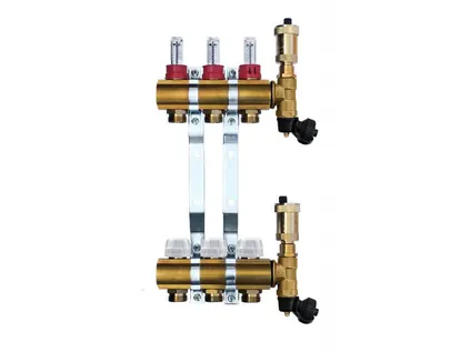
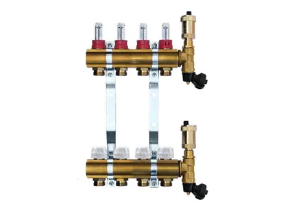
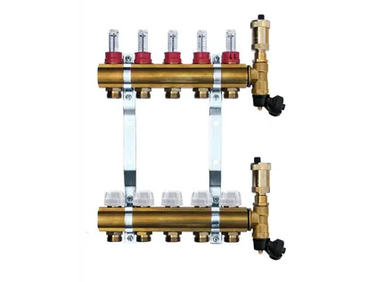
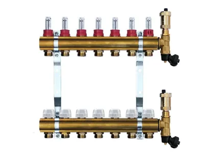
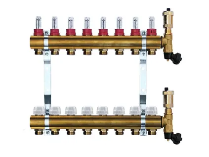
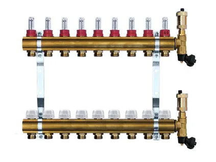
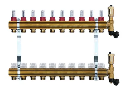
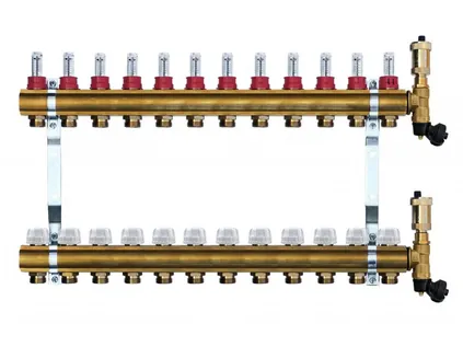
H.P.W. brass manifold – 2 circuits
- Number of circuits2
- Flow / return connection1"
- Circuit outletsEK (Eurocone)
- Flow meters0–5 l/min
- Length without / with ball valves145 / 230 mm
Manifold with flow meters, integrated thermostatic valves and an aluminium bracket, made of brass profile tube – from 2 to 12 circuits, manufactured in-house in Slovakia. Available to homeowners from the ATRIASHOP.EU online store and to partners as OEM products.
updateUpdated: verifiedTechnically reviewed by the ATRIA SK s.r.o. technicians
The manifold is where heating water from a single source – a boiler, a heat pump or a mixing unit – is distributed to the individual underfloor (or radiator) heating circuits, and where it returns from them again. Each circuit on the manifold can be regulated, bled and, if necessary, shut off completely on its own, without taking the rest of the house out of operation. If, for example, you are repairing the floor in one room, you simply close that room's circuit and the other rooms keep heating.
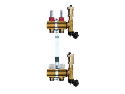
We manufacture H.P.W.® manifolds from brass profile tube. According to the production documentation, these are hot-formed brass bars made from high-quality CDA 360 brass profiles; the fittings are made of Press-Messing Ms 58 with a nickel-plated finish. The upper bar (flow) carries flow meters with a 0–5 l/min range, while the lower bar (return) has integrated thermostatic valves onto which thermostatic heads or actuators are fitted directly. The whole assembly is mounted on an aluminium bracket.
All you need to add are compression fittings for your pipe (for PEX-AL-PEX 16 × 2, two per circuit) and, as required, 1" ball valves with thermometer and a manifold cabinet. You will find all accessories on the page Accessories: valves, cabinets, pipe.
We optimised the design of the new generation of H.P.W. manifolds to make installation in the cabinet as simple as possible and to keep the whole installation as narrow as possible.
The flow and return bars are made of brass profile tube. The Press-Messing Ms 58 fittings are nickel-plated and ready for many years of service in a heating system.
The flow meters on the flow bar measure in the 0–5 l/min range with an accuracy of ±10 %. They are dual-regulating and the setting can be locked so that it does not change during later handling.
The return valves are integrated directly in the return bar. Thermostatic heads or actuators are fitted onto them without any additional adapters.
Thanks to the compact spacing between the valves, the overall width of the installation is minimal – each additional circuit adds only 50 mm to the length of the manifold.
The manifold is mounted on an aluminium bracket. With quick-mount technology it is simply hung onto the brackets in the cabinet and secured with screws.
An automatic air vent and a drain valve are included in the delivery. The air vent is also available in a manual version.
All sizes come with the same equipment: 1" flow and return connections, EK (Eurocone) circuit outlets, 0–5 l/min flow meters, shut-off valves, an automatic air vent and a drain valve. Prices and availability on the product cards are loaded directly from the ATRIASHOP.EU online store.


The length determines which cabinet the manifold will fit into. Ball valves add 85 to 90 mm to the assembly.
| Circuits | Code | Length without ball valves | Length with ball valves | Cabinet flush-mounted / surface-mounted |
|---|---|---|---|---|
| 2 | ROZDZ.02H | 145 mm | 230 mm | 1300HPX / 1210HPX |
| 3 | ROZDZ.03H | 195 mm | 280 mm | 1310HPX / 1210HPX |
| 4 | ROZDZ.04H | 245 mm | 330 mm | 1310HPX / 1210HPX |
| 5 | ROZDZ.05H | 295 mm | 380 mm | 1320HPX / 1210HPX |
| 6 | ROZDZ.06H | 345 mm | 430 mm | 1320HPX / 1220HPX |
| 7 | ROZDZ.07H | 395 mm | 480 mm | 1325HPX / 1220HPX |
| 8 | ROZDZ.08H | 445 mm | 535 mm | 1325HPX / 1225HPX |
| 9 | ROZDZ.09H | 495 mm | 585 mm | 1325HPX / 1225HPX |
| 10 | ROZDZ.10H | 545 mm | 635 mm | 1330HPX / 1225HPX |
| 11 | ROZDZ.11H | 595 mm | 685 mm | 1330HPX / 1230HPX |
| 12 | ROZDZ.12H | 645 mm | 735 mm | 1340HPX / 1230HPX |
The cabinet recommendation assumes a manifold with ball valves and a clearance of at least 100 mm for connecting the flow and return pipes and working with a spanner. If you are also planning a pump or mixing group, you will need a larger cabinet. Detailed guidance can be found on the page Manifold cabinets.
The manifold is supplied as a complete assembly ready for installation. You only buy the parts that depend on the specific installation – pipe, compression fittings, ball valves, cabinet and controls.
| Part | Included | Note |
|---|---|---|
| Brass flow and return bars | yes | 1" inlet and outlet connection, EK (Eurocone) circuit outlets |
| Flow meters on the flow bar | yes | 0–5 l/min, accuracy ±10 %, double-regulation type with a locking option |
| Thermostatic valves on the return bar | yes | integrated in the bar, for thermostatic heads or actuators |
| Circuit shut-off valves | yes | each circuit can be closed separately |
| Automatic air vent | yes | manual version also available in a made-to-measure assembly |
| Drain valve | yes | filling, flushing and draining the system |
| Aluminium bracket | yes | quick installation – hang the manifold on the brackets and tighten the screws |
| 1" ball valves with thermometer | no – buy separately | a pair: red for the flow, blue for the return, straight or angled – ball valves for the manifold |
| 16 × 2 EK compression fittings | no – buy separately | 2 pcs per circuit (500684 or RCS16) |
| Manifold cabinet | no – buy separately | flush-mounted 1300HPX – 1350HPX or surface-mounted 1210HPX – 1250HPX – manifold cabinet |
| Pipe for the floor | no – buy separately | PEX-AL-PEX 16 × 2 recommended – pipe and installation materials |
| Thermostatic heads or actuators | no – depending on the controls | check the connection before buying – see the guide to installing an underfloor heating manifold |
The manifold can be fixed with the supplied brackets in a cabinet or directly to a wall on a sufficiently strong base. We do recommend a cabinet, however – it protects the manifold, hides the bundle of pipes and keeps the valves accessible.
The configuration of an H.P.W. manifold depends entirely on the customer's needs. The basis is always the brass body with flow meters and thermostatic valves in the required number of circuits. To this you add three main equipment options, which determine how the manifold will be installed and operated.
For a typical installation in a family house, the standard assembly from the ATRIASHOP.EU online store is all you need. If you are an installation company, a wholesaler or a manufacturer of underfloor heating systems and need a different configuration, we will prepare a custom assembly for you – see the section Production and OEM.
An automatic air vent removes air continuously without any attention – it is more convenient especially in the first weeks of operation, when dissolved air is released from the water. A manual air vent is simpler and is used to bleed the system as needed.
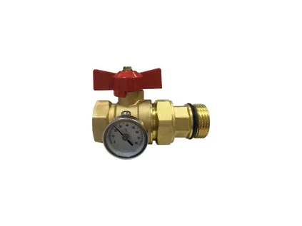
1" ball valves on the flow and return let you isolate the entire manifold with a quarter turn. We offer them in straight and angled versions, with a 0–80 °C thermometer and a colour-coded butterfly handle (red for flow, blue for return).
Compression fittings connect the circuit pipes to the EK outlets. For the recommended PEX-AL-PEX 16 × 2 pipe, use the ALPEX 16 × 2 ALU-EK fitting – you need two for each circuit.
Each room has at least one circuit, larger rooms two or more. A rough calculation can be found in the table below. Choose a manifold from ROZDZ.02H to ROZDZ.12H according to the number of circuits.
We always recommend them – as a pair (red + blue). Straight valves if the pipe from the heat source arrives from the side, angled valves if it comes from below or above.
Two for each circuit (flow + return). For 8 circuits, that means 16 compression fittings 16 × 2 EK.
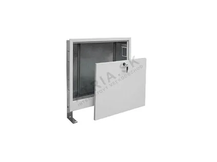
Flush-mounted for new builds or renovations where the wall is chased out, surface-mounted for retrofit installation. The length table above will help you choose.
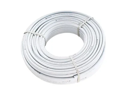
PEX-AL-PEX 16 × 2 pipe with oxygen barrier, pipe clips and a system board. Calculate the amount of pipe from the floor area and the pipe spacing.
Thermostatic heads or actuators on the return; with a higher source temperature, a mixing unit and a safety contact thermostat. The procedure is described in the installation and setup guide.
Technical data common to all H.P.W. manifold sizes.
| Parameter | Value |
|---|---|
| Application | heating and cooling systems |
| Permissible fluid temperatures | -10 °C to 120 °C |
| Max. permissible operating temperature | +80 °C |
| Max. working pressure | 4–6 bar |
| Max. permissible operating pressure | 6 bar |
| Max. test pressure | 10 bar |
| Flow meter measuring range | 0–5 l/min |
| Measuring accuracy | ±10 % |
| Flow rate | 1.12 m³/h |
| Flow meters | dual-regulating, lockable |
| Material | brass |
| Fittings | Press-Messing Ms 58, nickel-plated |
| Seals | EPDM |
| Flat gasket | WS 3825 |
| Thread | DIN ISO EN 228-1 |
| Sound insulation | DIN 4109 |
| Fluids | heating water, cooling water, water mixtures with a standard anti-corrosion antifreeze additive |
| Flow and return connection | 1" |
| Branch (circuit) connection | EK, Eurocone |
| Number of circuits | 2 to 12 |
| Manifold length without ball valves | 145 mm (2 circuits) to 645 mm (12 circuits) |
| Manifold length with ball valves | 230 mm (2 circuits) to 735 mm (12 circuits) |
| Recommended pipe | PEX-AL-PEX 16 × 2 |
| Recommended connection | ALPEX 16 × 2 ALU-EK compression fitting |
| Recommended cabinets | manifold cabinets, surface-mounted and flush-mounted |
| Country of origin | Slovakia |
The exact length of each size can be found in the dimensions table above. Always make sure that the operating temperature and pressure in the system do not exceed the values given in the table.
Hot water from the heat source enters the upper bar (flow) through the 1" connection. From there it is distributed to the individual circuits – each circuit is one loop of pipe laid in the floor of a particular room. At the start of each circuit there is a flow meter, which shows how many litres of water per minute are flowing through that circuit and also lets you set this flow rate. The water passes through the loop, gives off its heat to the floor and returns to the lower bar (return). Here each circuit has a thermostatic valve, which can be operated by a thermostatic head or by an actuator controlled by a room thermostat.
The circuits in a house are never the same length. A bathroom may have 40 metres of pipe, a living room two circuits of 90 metres each. Water always takes the path of least resistance – without balancing, short circuits would receive too much water and long ones too little. You know the result: an overheated floor in the bathroom and cold spots in the living room. The flow meters on the H.P.W. manifold even out this difference. You set each circuit to a flow rate appropriate to its length and heat demand – this is called hydraulic balancing. A step-by-step procedure with an example can be found in the guide Installing and setting up the manifold.
The integrated thermostatic valves on the return allow each room to be controlled individually. The simplest solution is a thermostatic head fitted directly on the valve. A more convenient option is to fit actuators on the valves and control them with room thermostats in the individual rooms – the circuit then closes when the room is warm enough and opens again when the temperature drops. When choosing a thermostatic head or actuator, check that it matches the valve connection on the manifold; we will be glad to help you choose.
The H.P.W. manifold is primarily designed for underfloor heating, but it works just as well in a manifold-based (star) radiator distribution system. Each radiator is then connected by its own pair of pipes directly from the manifold, with no branches or joints in the floor. Such a system is easy to design, and individual radiators can be balanced separately and isolated in the event of a fault. For radiators with bottom connection, the HPW Set2 regulating set is a suitable choice – you will find it among the accessories.
In systems that provide cooling in summer (for example with a reversible heat pump), chilled water can also flow through the manifold. When cooling via the floor, keep the water temperature high enough that no moisture condenses on the floor surface or on the pipes – leave this setting to the system designer or the supplier of the cooling source.
When choosing an underfloor heating manifold, the number of circuits is not the only thing that matters. Just as important are how the system will be regulated, what pipe you will use, where the manifold will be located and what heat source the water will come from. These seven points will help you choose the right model and avoid buying parts at the last minute.
Count the circuits by room and area – an indicative table is below. If you land on a borderline number, choose a manifold with one more circuit. An unused circuit stays closed by its shut-off valve and comes in handy when you later extend the system, for example into the loft or a conservatory. H.P.W. manifolds are normally available from 2 to 12 circuits in the online store.
Flow meters on the flow bar show the flow through each loop in l/min and let you adjust it. Without them, circuits of different lengths can hardly be balanced at all. All H.P.W. manifolds have double-regulation flow meters of 0–5 l/min with an accuracy of ±10 % and the option of locking the setting.
If you want a different temperature in every room, you need valves on the return that take thermostatic heads or actuators. The H.P.W. manifold has them integrated directly in the lower bar, so there is no need to buy them separately.
The circuit outlets have an EK (Eurocone) connection, to which the pipe is connected by a compression fitting. The fitting size must match the pipe exactly – for the recommended PEX-AL-PEX 16 × 2, use a 16 × 2 EK fitting, two for each circuit.
Functionally, both types do the same thing. The H.P.W. brass manifold is made in Slovakia, has compact spacing (each circuit adds only 50 mm) and you can customise its equipment. Choose a stainless steel manifold if the project requires it, or if you want heads with an M30 × 1.5 connection. You will find a comparison in the section brass or stainless steel manifold.
A manifold with ball valves is 230 mm (2 circuits) to 735 mm (12 circuits) long. Choose the cabinet according to this length, with a reserve of at least 100 mm for the connections – the recommended combinations are in the dimensions table above.
The maximum permissible operating temperature of the manifold is +80 °C, but underfloor heating works with a much lower water temperature. With a high-temperature source, therefore, allow for mixing and a safety thermostat – more in the use section below and in the guide installing and setting the manifold.

Approximate calculation for 16 × 2 mm pipe. We recommend that a single circuit, including the supply section from the manifold, should not exceed approximately 80–100 m of pipe. The table assumes a maximum of 85 m of pipe within the floor of the room itself, leaving a reserve for the supply sections.
| Room (example) | Area | Pipe at 15 cm spacing (≈ 6.7 m/m²) | Pipe at 10 cm spacing (≈ 10 m/m²) | Recommended number of circuits (15 cm / 10 cm) |
|---|---|---|---|---|
| WC, small bathroom | 5 m² | ≈ 34 m | ≈ 50 m | 1 / 1 |
| Bathroom | 8 m² | ≈ 54 m | ≈ 80 m | 1 / 1 |
| Hallway, entrance area | 10 m² | ≈ 67 m | ≈ 100 m | 1 / 2 |
| Children's room, study | 12 m² | ≈ 80 m | ≈ 120 m | 1 / 2 |
| Bedroom | 16 m² | ≈ 107 m | ≈ 160 m | 2 / 2 |
| Larger bedroom, kitchen | 20 m² | ≈ 134 m | ≈ 200 m | 2 / 3 |
| Living room | 25 m² | ≈ 168 m | ≈ 250 m | 2 / 3 |
| Living room with dining area | 30 m² | ≈ 201 m | ≈ 300 m | 3 / 4 |
| Living room with kitchen | 40 m² | ≈ 268 m | ≈ 400 m | 4 / 5 |
This is a general recommendation, not a system design. The actual number of circuits, pipe spacing and water temperature are determined by a heat loss calculation. A 10 cm spacing is usually chosen where heat demand is higher (bathrooms, perimeter zones by large windows), 15–20 cm in ordinary living spaces.
When designing the system, work room by room. Calculate the area that will actually be covered by pipe (excluding kitchen units, built-in wardrobes or the bath), multiply it by the pipe requirement for the chosen spacing and divide the result into circuits so that none of them exceeds the recommended length. Add the supply section to the length of each circuit – the distance from the manifold to the room and back.
Ground floor of a family house: living room with kitchen 40 m² (4 circuits at 15 cm spacing), bedroom 16 m² (2 circuits), children's room 12 m² (1 circuit), bathroom 8 m² (1 circuit) and hallway 10 m² (1 circuit). That makes 9 circuits in total – the ROZDZ.09H manifold is suitable, or ROZDZ.10H with one circuit in reserve. With ball valves, the ROZDZ.09H is 585 mm long, so it fits comfortably into the 1325HPX flush-mounted cabinet.
A system board with a grid for laying the pipe, pipe clips and PEX-AL-PEX pipe can be found on the page Pipe, fittings and system board, and a comparison of brass and stainless steel manifolds in the section Stainless steel manifolds. Circulation pumps and thermostats for underfloor heating are available at avansa-europe.com.
The brass manifold is universal – the same model works with a condensing boiler, a heat pump or a solid-fuel boiler. What differs is only what goes between the heat source and the manifold.
A condensing boiler works most efficiently at a low return temperature, which is why it suits underfloor heating well. If the boiler supplies only the underfloor heating and its control (for example weather-compensated) keeps the water temperature low, the manifold can be connected directly. If the same boiler also supplies radiators or heats a cylinder, the water for the underfloor heating is prepared in a separate mixing circuit.
A heat pump and underfloor heating are a natural pair – both work with a low water temperature. H.P.W. manifolds are designed for both heating and cooling systems, so with a reversible heat pump they can also be used for floor cooling. When designing, compare the total flow of the system with the manifold flow value of 1.12 m³/h from the technical specifications.
These sources supply water at a temperature intended for radiators, and the underfloor heating must never be connected to them directly. Between the source and the manifold there belongs a mixing valve with a circulation pump and a clamp-on safety thermostat that switches off the underfloor heating pump if it overheats. You will find suitable pumps, clamp-on thermostats and room thermostats on avansa-europe.com.
A common combination: underfloor heating on the ground floor, radiators upstairs or in the bathroom. The H.P.W. manifold can also supply radiators in a manifold (star) layout – each radiator has its own pair of pipes from the manifold, and you set its flow with the flow meter. The HPW Set2 control set is designed for radiators with a bottom connection.
In a renovation where there is no height for a classic wet system with screed, a dry underfloor heating system with the same PEX-AL-PEX 16 × 2 pipe is used. The manifold is connected in the same way – with compression fittings on the EK outlets.
Most problems with underfloor heating are not caused by the manifold itself but by an ill-chosen assembly. These mistakes are easy to avoid at the time of purchase:
If you are not sure, write to us at info@atria.sk with the room areas and the heat source – we will be glad to advise you on the number of circuits and the choice of assembly. A heating installer can also work out the pipe requirement and the number of circuits and boards for you.
H.P.W.® manifolds are manufactured by ATRIA Slovensko, based in Žilina, Slovakia. We produce high-quality H.P.W. manifolds and other brass and stainless steel solutions for our clients' specific requirements. The country of origin of the manifolds is Slovakia, and as the manufacturer we can advise you both on configuring the assembly and on technical questions during installation.
Thanks to our wide range of accessories, we can ensure the right connection in every installation: connection adapters, flow meters, ball, regulating or zone valves, thermometers, pressure gauges, air vents and controls.
Partner pricing and terms of cooperation are available from ATRIA Europe – wholesale for partners. For OEM and export enquiries, contact chobotova@atria.sk or +421 905 729 483; for a specific technical solution, write to info@atria.sk or call +421 917 133 662 (Monday – Friday, 7:30 – 15:30 CET).
Goods are shipped by courier for the fastest and safest delivery.
Packaging of the assemblies adapted to the customer's needs and requirements.
Air vents, ball valves, fittings and other components according to the customer's needs.
End customers buy at ATRIASHOP.EU, partners via atria-europe.com.

Positioning, pipe connection, pressure test and balancing with the flow meters, step by step.
Viewarrow_forward
Straight and angled 1" ball valves with thermometer, HPW Set2 regulating set for radiators.
Viewarrow_forward
Flush-mounted and surface-mounted cabinets with adjustable height and depth – which one fits which manifold.
Viewarrow_forward
A stainless steel alternative with 0–5 l/min flow meters and M30 × 1.5 thermostatic valves.
Viewarrow_forwardManifolds from 2 to 12 circuits, ball valves, cabinets, pipe and compression fittings with current prices and availability. We will be happy to help you choose and configure your assembly on our technical line +421 917 133 664 (Monday – Friday, 7:30 – 15:30 CET).
Short videos showing the products, installation and settings.
Our technician usually replies on the same working day.
call+421 917 133 664 · mailinfo@atria.sk
All our brands, specialist websites and online stores in one place.